Cryogenic Chamber Sensor Harnesses: Engineering Considerations from Termination to Delivery Quality
Starway Technology’s experience and observations in harness assembly for specialized environments
When a sensor harness is installed inside a cryogenic vacuum chamber, engineers focus on signal integrity and installation conditions. Purchasing teams need requirements to become deliverable products, while quality teams need clear criteria for checking every connection. All three roles share a central question: have the harness’s critical risks been addressed?
Starway Technology’s participation in cryogenic chamber sensor harness assembly has deepened our understanding of the relationship between harness manufacturing and equipment integration. A harness must connect materials, termination methods, installation needs, and inspection requirements as well as electrical circuits. This article shares manufacturing observations without disclosing customer identities, drawings, part numbers, or system configurations.
Technical Overview
Evaluating a cryogenic sensor harness requires a coordinated review of material compatibility, termination methods, mechanical stress, thermal anchoring, vacuum compatibility, and inspection requirements. Starway Technology shares a manufacturing perspective to help customers clarify process conditions and verification responsibilities.
This article focuses on sensor harnesses inside cryogenic chambers. Such equipment may support fields including quantum computing research. The assembly work discussed here does not establish a claim of complete quantum computer wiring capability.
Compatibility Before Assembly
Confirm the relationship between wires, contacts, and tools, and resolve questions before production.
Alignment with Installation Needs
Understand wire-length allowances, fixing locations, and temperature-stage requirements to define manufacturing and installation interfaces.
Clear Quality Verification
Define inspection purposes, acceptance criteria, and environmental verification responsibilities so quality requirements have a shared meaning.
1. Understand the Harness’s Role in the Equipment
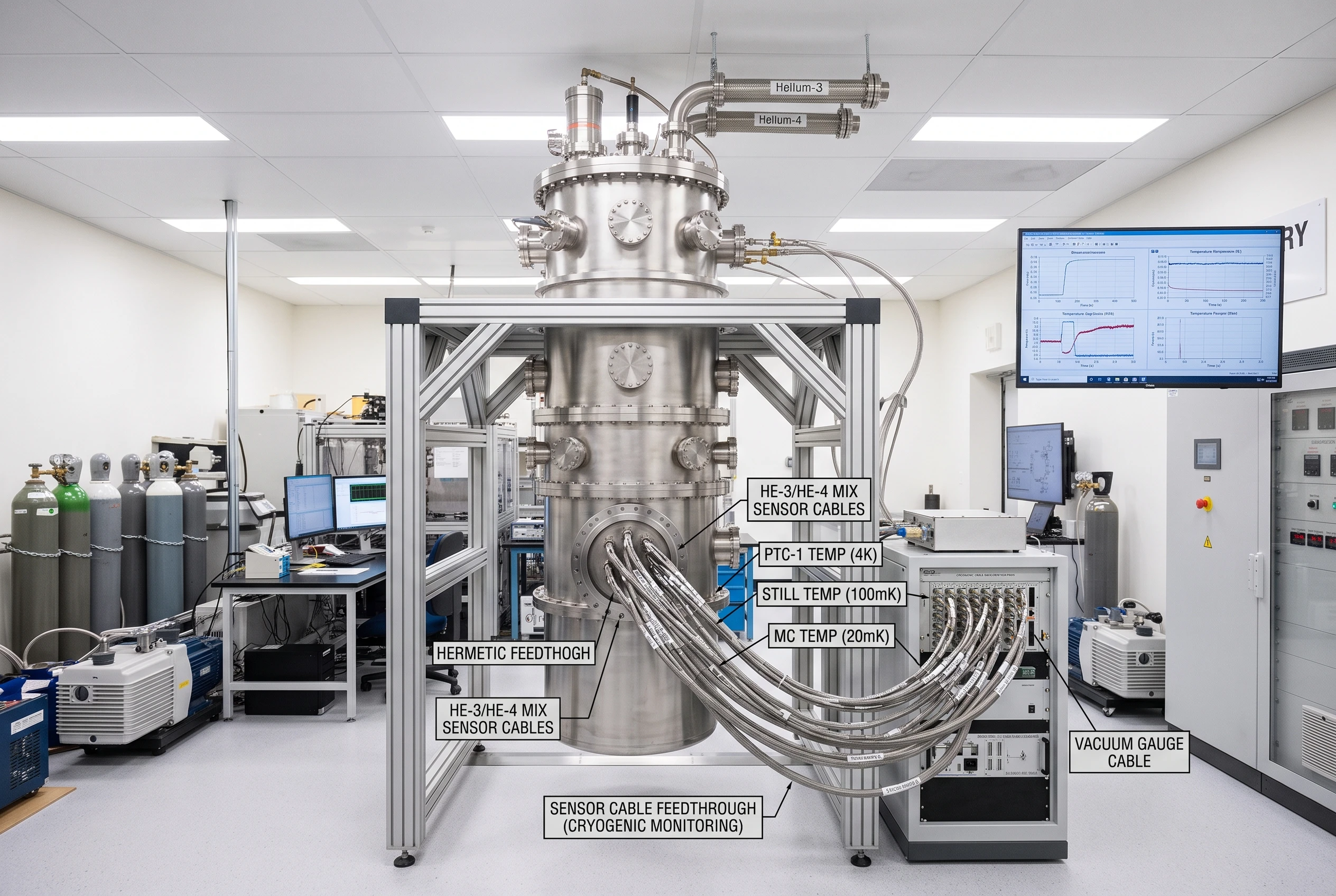
The assembly work involved temperature sensor harnesses inside a cryogenic chamber, connecting sensing elements to measurement interfaces. Depending on the system design, signals may pass through intermediate connectors and vacuum feedthroughs to external equipment.
Manufacturing preparation requires more than contact counts and wire lengths. It must identify which sections operate under vacuum, the temperature conditions along the wiring, connector locations, and the respective responsibilities of the harness manufacturer and equipment integrator. Different operating environments may require different termination and fixing methods.
For module manufacturers and system integrators, clarifying these conditions early helps confirm manufacturing feasibility and reduces later revisions caused by different interpretations of the interfaces.
2. Fine-Wire and Contact Compatibility Comes Before Processing
Cryogenic wiring must manage the heat carried by conductors toward colder regions. Wire diameter is one factor; conductor material, length, and temperature range also matter. Some low-temperature sensor wiring uses alloy conductors with relatively low thermal conductivity. Selection must also consider electrical properties, mechanical strength, and sensor requirements.
As conductors become finer, insulation removal, handling, termination, and harness dressing become more sensitive. Complete insulation removal, conductor integrity, and loads on terminations cannot be judged from a neat finished appearance alone.
Starway Technology’s approach is to confirm material-to-contact compatibility before selecting a manufacturing method. Crimped contacts require checks against the supplier’s permitted conductor and insulation dimensions, tooling, and processing instructions. Soldered terminations require assessment of insulation removal, solderability, and heat input according to material and component requirements. Conditions outside the supplier’s specified range should be discussed with the customer before defining a solution and its verification basis.
For customers, this brings uncertainties into the discussion before processing begins. A room-temperature continuity check establishes the electrical connection at that moment. Mechanical strength and operating-environment compatibility require their own appropriate verification methods.
3. Critical Component Processing: Quantum Computer Sensors and special twist Wiring
In cryogenic equipment associated with quantum computing, sensors for quantum computers and special twist lead assemblies form important parts of the temperature-measurement chain. Processing must address wiring assignments, termination integrity, mechanical loading, and measurement conditions. To protect commercial confidentiality, this section explains component functions and process controls without identifying brands, models, wire dimensions, or system configurations.
1. Material Verification and Process Preparation
Verify sensors, special twist wiring, termination methods, and installation requirements against approved documentation. Maintain the relationship between materials, document revisions, and circuit functions. Conductor materials, insulation, and twisted-wire construction must be assessed for the intended environment; ordinary industrial wire processing conditions should not be applied automatically.
Operator Protection and Clean Handling
When processing or assembling sensors, fine wires, contacts, and vacuum-side connectors, operators must wear clean gloves and masks appropriate to the work. Avoid bare-hand contact with sensors, exposed conductors, contacts, and vacuum-side wiring surfaces.
Gloves reduce contamination from fingerprints, perspiration, and skin oils. Masks help reduce exposure to moisture and droplets from exhaled breath. Replace contaminated or damaged gloves promptly, and keep materials, tools, and work surfaces clean. For ESD-sensitive components, gloves and workstations must support the applicable ESD controls.
Gloves do not completely block heat from the hands. Minimize prolonged handling of sensors and use suitable fixtures or tools where needed. Allow the sensor and test environment to reach thermal equilibrium before checking functional readings to reduce transient effects from hand warmth. Moisture control also depends on environmental, cleaning, and drying requirements.
2. Identify Twisted Pairs and Manage Wire Assignments
Before separating special twist wiring, identify pairs from the wire construction and markings. Assign excitation and sensing functions according to the wiring documentation and establish traceable identification immediately. Continuity testing confirms the two ends of an individual conductor; it does not independently identify the original twisted pairs. Preserve the required twist near terminations and minimize unnecessary untwisted length.
3. Confirm Sensor Terminations and Four-Wire Measurement Connections
Where four-wire measurement is used, configure excitation and voltage-sensing paths according to sensor and instrument requirements, and confirm polarity and termination locations. Separate sensing paths help reduce lead-voltage-errors, while appropriate twisted-pair arrangements help suppress induced noise. Detailed wire assignments, contact mappings, and configurations remain in project documentation.
4. Insulation Removal, Conductor Inspection, and Soldering
Select processing methods according to insulation materials and component requirements. After stripping, inspect for residue, conductor damage, and deformation. Control heat input, solder use, and mechanical loading during soldering, then perform suitable cleaning and magnified inspection. Use confirmed process documentation to prevent excessive heat exposure and conductor damage.
5. Strain Relief, Installation, and Thermal Anchoring
Retain the wire-length allowance needed for installation so cooling-related contraction does not pull on terminations. Confirm sensor thermal contact with the measured surface and lead anchoring across temperature stages according to the equipment design. Check curing conditions and environmental compatibility of fixing materials. Mechanical fixing and thermal anchoring serve different purposes and must be addressed separately.
6. Verify Wiring and Termination Quality in Stages
Before connecting the sensor, verify individual conductor mappings and circuits that must remain isolated. After connection, check polarity, terminations, and unintended connections against the approved circuit. Measurement paths intentionally joined by design must not be treated as shorts. Test currents, voltages, and methods must respect component limits rather than automatically applying standard harness test conditions to sensitive sensors.
7. Equipment Settings and Functional Checks
At the equipment interface, confirm sensor input type, excitation conditions, measurement range, and applicable calibration data. Perform functional checks under suitably stable conditions. A displayed reading alone does not confirm that the settings are correct. Agree on the responsible parties, conditions, and acceptance criteria for environmental and equipment-level verification.
4. Ceramic Connectors and Contacts for Quantum Computers: Dedicated Hand Tools and Assembly
Specialized wiring interfaces require compatibility between ceramic connectors and contacts for quantum computers and dedicated hand tools. This section retains process and quality-control considerations while keeping component part numbers, contact counts, tool models, and processing settings confidential.
| Component / Tool | Process Role and Verification Priorities |
|---|---|
| Ceramic connector for quantum computers | Provides a wiring interface for specialized environments. Confirm compatible contacts, assembly orientation, and mating components. The connector itself is not a complete vacuum-sealed feedthrough. |
| Matching contacts | Establish electrical connections between conductors and the connector interface. Confirm conductor, contact, and termination compatibility. |
| Dedicated hand tool | Completes contact termination with the specified positioning accessory. Confirm tool condition, suitability, and approved settings. |
| Dedicated positioning accessory | Locates the contact so crimping acts on the specified region. |
| Dedicated insertion and extraction tools | Install compatible contacts or release their retention mechanism. Follow the specified method to avoid pulling directly on the wires. |
1. Confirm Fine-Wire and Contact Compatibility
Check conductor dimensions, construction, and the contact’s permitted range. A fine conductor fitting inside a contact does not establish crimp compatibility. Resolve uncertainties through a supplier-confirmed solution before defining processing and verification conditions. Folding wires, combining conductors, or adding solder must not be used as improvised substitutes for compatibility confirmation.
2. Verify Tools, Documentation, and Cleanliness
Before processing, verify connectors, contacts, wires, and wiring documents, and confirm that the dedicated hand tool matches its positioning accessory. Select processing settings according to contact and conductor requirements. Where calibration, gauging, or first-piece checks apply, follow the relevant documentation and retain records.
Contact and connector assembly also requires clean gloves and masks to reduce contamination from fingerprints, perspiration, and exhaled moisture. Keep tools and assembly areas clean.
3. Strip Wires and Prepare Contacts and Accessories
Set stripping conditions according to contact and process documentation. Inspect for conductor damage, residual insulation, and loose strands. Complete any required wire routing or accessory preassembly before inserting the conductor to its specified position in the contact. Detailed dimensions and processing settings remain in controlled documents.
4. Position, Crimp, and Inspect
Use the dedicated positioning accessory to hold the contact correctly, then complete the crimp with the dedicated hand tool at approved settings. Inspect conductor position, crimp impressions, contact condition, and insulation clearance. Where pull testing or other destructive verification is required, use separately prepared samples under agreed conditions. Pulling on deliverable assemblies is not a substitute for a defined test.
5. Contacts and Verify Retention and Wiring
After crimp inspection, contacts using the specified tools and sequence. Confirm the connector’s mating-face and wiring-face views to prevent orientation errors. Verify contact position and retention, then check wire assignments against the approved wiring table. Insertion feel or wire color alone is insufficient confirmation.
6. Dress the Harness, Verify Electrically, and Control Rework
Dress the completed harness and provide strain relief according to installation needs, avoiding concentrated bending and pulling loads at terminations. Electrical checks must respect the sensor circuit and component limits. For rework, release the retention mechanism with the dedicated insertion or extraction tool according to the specified method. Reinspect contacts, connectors, and wiring after removal and reassembly; do not extract contacts by pulling on the wires.
5. Harness Fixing Must Address Mechanical and Thermal Requirements
Different materials may contract by different amounts as a cryogenic chamber cools. Wiring that is too taut or fixed in unsuitable locations can place additional stress on terminations. Wire-length allowances, routing, and strain relief must therefore follow actual installation conditions.
Mechanical fixing controls harness loads. Thermal anchoring allows conductors to exchange heat with thermal masses at suitable temperature stages, helping control heat leakage toward colder regions. Both must follow the equipment and sensor installation design.
From a manufacturing perspective, it is essential to know which lengths, branches, and fixing sections must be preserved and which adjustments require engineering approval. Neat assembly is a basic requirement; compatibility with installation and thermal design completes the assessment.
6. Vacuum Compatibility Includes Auxiliary Materials
Material assessment for vacuum environments extends beyond wires and connectors to heat-shrink tubing, labels, adhesives, and process residues. Their outgassing and contamination risks may affect the chamber environment and sensitive components.
Vacuum-boundary sealing and leakage requirements are separate from the compatibility and cleanliness of materials inside the chamber. A waterproof connector rating does not establish vacuum or cryogenic suitability.
Starway Technology considers changes to auxiliary materials part of the engineering review. Even a different sleeve, marking method, or fixing material should be checked against customer requirements. Small material changes can still affect the operating environment.
7. Turn Quality Requirements into Practical Inspection Criteria
For purchasing and quality teams, “inspected” needs a clear definition: which documents apply, what is checked, how acceptance is determined, and how records relate to the delivered product. Inspection plans should reflect harness construction, component limits, and customer acceptance requirements.
| Verification Item | Questions to Resolve |
|---|---|
| Wire mapping and continuity | Is verification based on an approved wiring table or drawing revision? Are required connections and circuits that must remain isolated checked separately? |
| Termination and visual condition | Are conductor integrity, insulation, solder joints or crimps, contact positioning, and strain relief assessed against applicable requirements? |
| Insulation performance | Where required, are test locations, voltages, and acceptance limits defined? Could testing affect connected sensors or components? |
| Revision control and traceability | Can materials, process documents, changes, and inspection records be traced to the delivered product? |
| Environmental and functional verification | Which checks belong to the harness manufacturer, and which require customer equipment? Is the verification scope clear? |
Open- and short-circuit checks, insulation resistance tests, and dielectric withstand tests answer different questions. One test should not replace the entire quality assessment. Where sensors are already connected, their limitations must also be considered.
Room-temperature manufacturing and delivery inspections should be distinguished from low-temperature cycling, vacuum testing, and equipment-level functional verification. Clear responsibilities and acceptance criteria give “qualified” a shared meaning. These recommendations describe manufacturing considerations, not tests claimed to have been completed on this project.
8. Specialized Projects Begin with Clear Requirements and Responsibilities
This assembly experience showed us how specialized harness projects span materials, connectors, manufacturing processes, and equipment installation. A manufacturer’s contribution includes identifying uncertainties, explaining their implications, and reaching practical agreements with the customer.
For purchasing teams, this creates a clear basis for discussing material supply, technical questions, and acceptance requirements before production. For engineers, it provides a manufacturing partner for evaluating compatibility, termination, and installation interfaces. For quality teams, it aligns inspection criteria, records, and verification responsibilities.
Starway Technology approaches different harness requirements through this engineering mindset: understand the product’s role, confirm processing conditions, discuss uncertainties early, and translate agreed requirements into manufacturing and quality controls. Clearly explaining capabilities, limitations, and areas requiring joint verification is part of responsible project cooperation.
Making Harnesses a Dependable Part of System Integration
Cryogenic chamber sensor harnesses show how individual termination details relate to wider system conditions. From fine conductors and contact compatibility to material suitability, installation loads, and inspection criteria, harness quality depends on continuity between requirements, manufacturing, and verification.
If your team is planning sensor harnesses, fine-wire terminations, or wiring for specialized environments, Starway Technology welcomes a technical discussion. Operating conditions, drawings or wiring requirements, specified materials, expected quantities, and acceptance criteria help define manufacturing feasibility, areas requiring confirmation, and the scope of cooperation.
FAQ | Frequently Asked Questions
Why should four-wire connections be evaluated for quantum computer sensors?
Four-wire measurement separates excitation and voltage-sensing paths to help reduce lead-voltage-errors. The twisted-pair arrangement of special twist wiring helps suppress induced noise. Wire assignments, polarity, and contact mappings must follow sensor and instrument requirements.
Can fine wires be crimped directly into the matching contacts?
First confirm conductor dimensions, construction, and the contact’s permitted range. A conductor fitting inside a contact, or use of a dedicated hand tool, does not establish compatibility. Resolve uncertainties with a supplier-confirmed solution before defining processing and verification conditions.
Why must operators wear gloves and masks?
Gloves reduce contamination from fingerprints, perspiration, and skin oils. Masks help reduce exposure to exhaled moisture and droplets. Gloves do not completely block hand warmth, so prolonged sensor handling should be minimized and thermal equilibrium established before checking functional readings.
Are mechanical fixing and thermal anchoring the same?
They serve different purposes. Mechanical fixing and strain relief control harness loads. Thermal anchoring allows conductors to exchange heat with thermal masses at appropriate temperature stages, controlling heat leakage toward colder regions. Both must follow the equipment installation design.
Does passing room-temperature continuity checks mean a harness has passed cryogenic verification?
No. Room-temperature continuity, termination inspection, insulation performance, low-temperature cycling, and equipment-level functional verification each serve different purposes. Test conditions must respect component limits, with verification scope, responsibilities, and acceptance criteria clearly agreed.