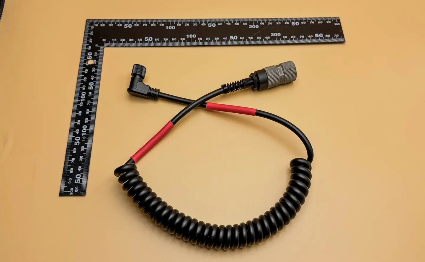
Tactical ANR Communication Spiral Cable Assembly for Armored Vehicles
A tactical communication spiral cable assembly for armored vehicles, featuring Amphenol Nexus U-329/U connector processing, 3.5mm TRRS signal mapping, custom PU spiral cable construction, 8-pin DIN connector integration, STP-file-based prototype validation, and custom 85% black PVC strain relief overmolding.
Tactical ANR Communication Spiral Cable Assembly for Armored Vehicles is a custom military communication cable assembly designed for armored vehicle communication systems. The assembly combines an Amphenol Nexus Technologies U-329/U connector side, a custom 8-pin DIN connector side, PU spiral cable construction, audio signal transmission, dedicated strain relief design, and final electrical verification.
This product demonstrates how Starway Technology supports military and aerospace harness manufacturing with connector-level workmanship control, customer STP file review, 3D-printed prototype validation, custom mold development, 85% black PVC strain relief overmolding, continuity testing, insulation resistance testing, individual connector protection, and traceable production records.
Official ILA Berlin 2026 Product Listing
This product is also featured in the official ILA Berlin digital product guide as Tactical ANR Communication Spiral Cable Assembly for Armored Vehicles . This external product listing helps connect Starway Technology's custom tactical cable assembly capability with ILA Berlin 2026 aerospace and defense industry visibility.
Technical Summary
Starway Technology manufactures tactical communication spiral cable assemblies for armored vehicle and high-reliability communication applications. This product uses an Amphenol Nexus Technologies U-329/U connector on one end and a customer-specific 8-pin DIN connector with custom strain relief on the opposite end.
The U-329/U side is wired to a 3.5mm TRRS signal assignment: Pin A connects to TRRS sleeve for GND, Pin B connects to TRRS tip for RIG_AFOUT, Pin C connects to TRRS ring 2 for PTT, and Pin D connects to TRRS ring 1 for RIG_AFIN. This mapping supports communication signal routing between the tactical connector interface and TRRS audio/control signal functions.
The cable uses a custom PU spiral cable construction for audio signal use, including power 2C in black and red plus two coaxial lines corresponding to TRRS signal paths. The 8-pin DIN side uses a customer-defined special shape and net-tail strain relief design. Based on the customer-provided STP file, Starway first supports 3D-printed prototype validation; after customer testing and approval, the project proceeds to custom mold development and 85% black PVC overmolding using a vertical injection molding machine.
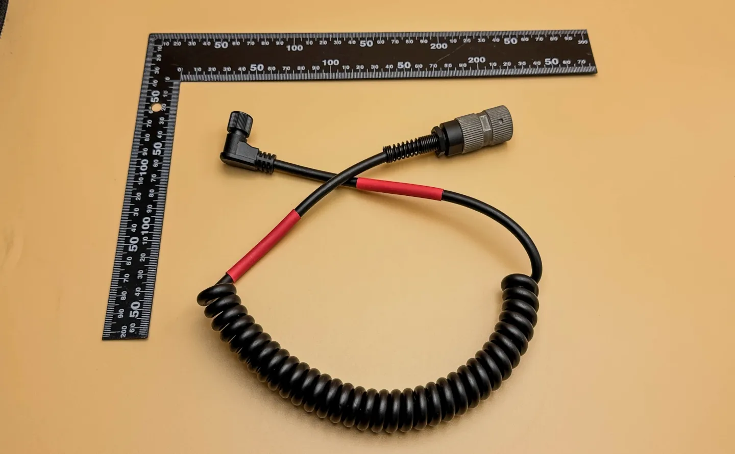
Finished tactical ANR communication spiral cable assembly for armored vehicle communication applications.
Product Design and Manufacturing Focus
Armored vehicle communication systems require stable audio signal transmission, reliable push-to-talk control, rugged connector handling, controlled cable flexibility, and mechanical protection against repeated movement. For this product, the design focus includes U-329/U connector termination, TRRS signal mapping, custom PU spiral cable processing, 8-pin DIN connector integration, strain relief overmolding, and final electrical verification.
Starway Technology Co., Ltd. supports this type of military communication cable assembly through customer drawing review, connector drawing reference review, STP file review, prototype preparation, spiral cable processing, soldering workmanship control, connector assembly using dedicated tools and torque control, electrical testing, individual connector packaging, and final inspection based on customer requirements.
U-329/U Connector Side
One end uses an Amphenol Nexus Technologies U-329/U connector with defined signal mapping to a 3.5mm TRRS interface.
Custom 8-Pin DIN SR Side
The opposite end uses an 8-pin DIN connector with customer-defined shape and custom net-tail strain relief overmolding.
PU Spiral Cable
The custom PU spiral cable includes power conductors and two coaxial signal lines for tactical communication signal transmission.
Key Product Specifications
- Application
- Tactical ANR communication, armored vehicle communication systems, military audio interconnects, and high-reliability communication cable assembly applications.
- U-329/U Connector End
- Amphenol Nexus Technologies U-329/U connector with soldering, connector assembly, dedicated tooling, and torque wrench-controlled assembly process.
- Signal Mapping
- U-329/U Pin A to 3.5mm TRRS sleeve for GND; Pin B to TRRS tip for RIG_AFOUT; Pin C to TRRS ring 2 for PTT; Pin D to TRRS ring 1 for RIG_AFIN.
- Custom 8-Pin DIN Connector End
- 8-pin DIN connector with customer-defined external shape and net-tail strain relief, supported by STP-file-based 3D prototype validation before tooling.
- Cable Construction
- Custom PU spiral cable for audio signal use, including power 2C in black and red plus two coaxial lines corresponding to TRRS signal functions.
- Overmolding Process
- 85% black PVC overmolding with a vertical injection molding machine. Adhesive is applied before injection because PVC and PU do not bond reliably without surface preparation.
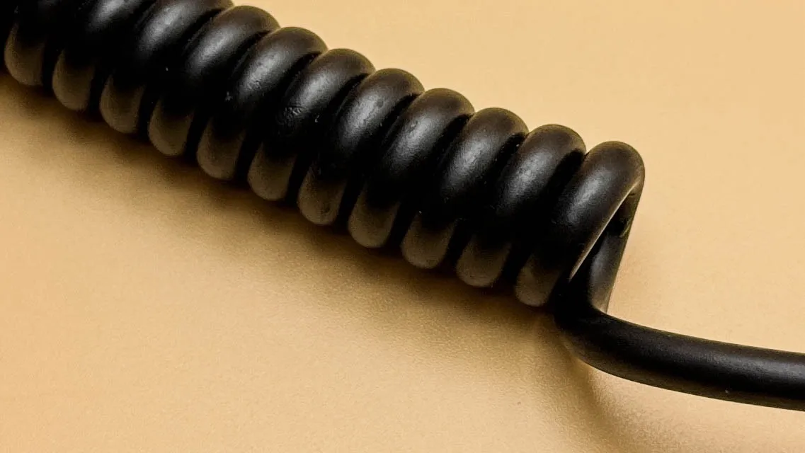
Custom PU spiral cable construction for tactical audio communication and armored vehicle cable routing.
Spiral PU Cable Construction
The cable uses a custom PU spiral cable structure because the product must support movement, recovery, and repeated handling in armored vehicle communication environments. Spiral cable processing is controlled before both cable ends are cut to the customer-specified final length.
The internal cable design includes power 2C in black and red plus two coaxial lines corresponding to TRRS signal paths. This structure supports tactical communication signal routing while maintaining the mechanical flexibility required for a spiral cable assembly.
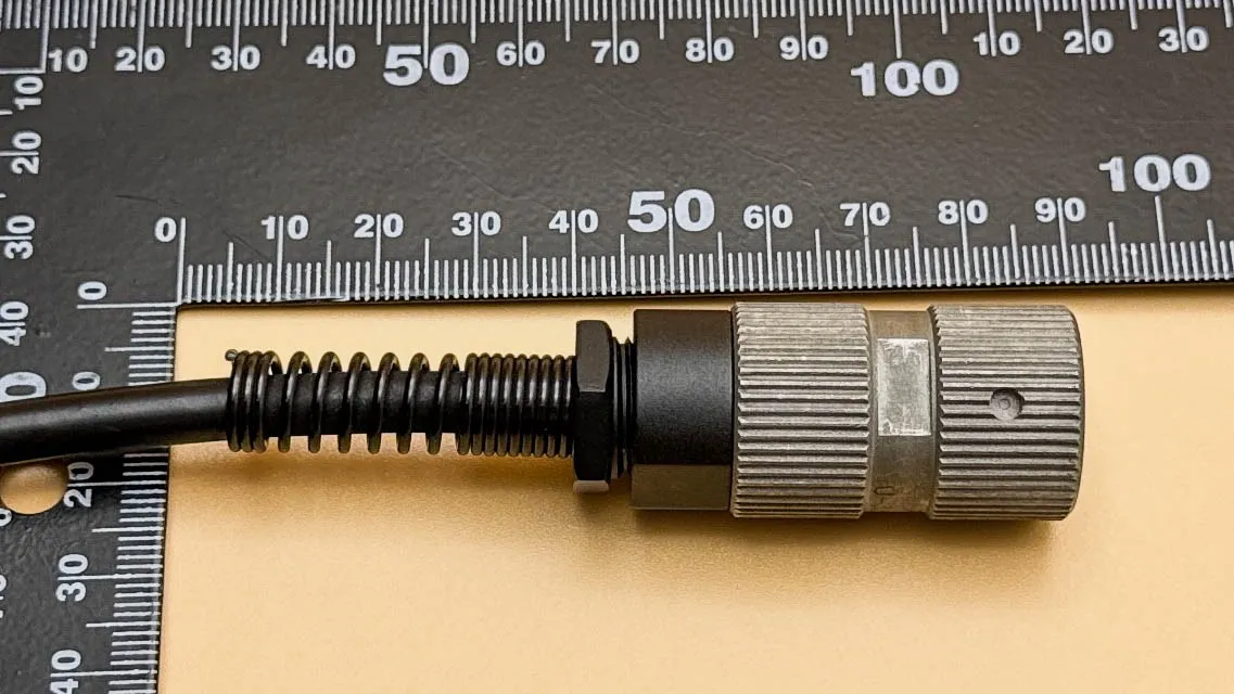
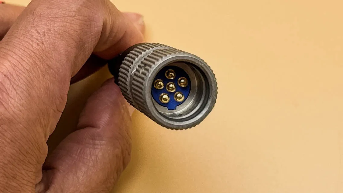
U-329/U connector side: Amphenol Nexus Technologies connector interface, soldering process, and assembly control.
U-329/U Connector and TRRS Pin Assignment
The U-329/U connector side uses Amphenol Nexus Technologies connector hardware. A connector drawing reference is available here: Amphenol / Nexus AP-146M-CP connector drawing reference .
The signal assignment for this cable assembly is defined as follows: Pin A connects to the 3.5mm TRRS sleeve for GND, Pin B connects to the TRRS tip for RIG_AFOUT, Pin C connects to TRRS ring 2 for PTT, and Pin D connects to TRRS ring 1 for RIG_AFIN.
- Pin A — GND / REF
- Connected to 3.5mm TRRS sleeve for ground reference.
- Pin B — AUDIO / SENSE-CMD
- Connected to 3.5mm TRRS tip for RIG_AFOUT.
- Pin C — PTT / REQN
- Connected to 3.5mm TRRS ring 2 for push-to-talk control.
- Pin D — MIC / DATA
- Connected to 3.5mm TRRS ring 1 for RIG_AFIN.
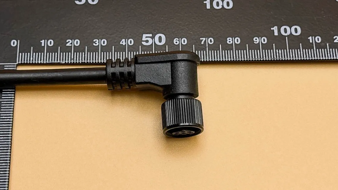
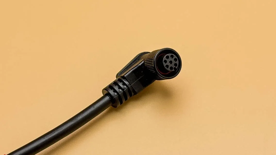
Custom 8-pin DIN connector side with customer-defined shape, net-tail strain relief, adhesive preparation, and 85% black PVC overmolding.
Custom 8-Pin DIN Overmolded Strain Relief Side
The opposite connector side uses an 8-pin DIN connector with a customer-defined special shape and net-tail strain relief. The customer provides the STP file, and Starway supports 3D-printed prototype preparation so that the customer can verify connector geometry, strain relief shape, cable exit direction, fit, and handling before tooling investment.
After customer testing and approval, the project moves to custom mold development and production. Because PVC and PU materials do not bond reliably by themselves, adhesive is applied to the overmolding area before injection. The strain relief is then formed using 85% black PVC and a vertical injection molding machine to complete the custom connector assembly.
From STP Prototype Validation to Molded Strain Relief Production
For military communication cable assemblies with custom connector geometry and strain relief requirements, prototype validation before tooling helps reduce mold revision risk. Starway Technology uses customer-provided STP files to support 3D-printed prototype preparation before mold investment.
OEM Manufacturing Process Flow
IPC-based workmanship thinking is closely related to the three practical quality principles: Function, Fit, and Form. For a tactical ANR communication spiral cable assembly, this means the cable must perform electrically, fit the connector and vehicle communication system correctly, and maintain acceptable workmanship appearance after assembly.
The following OEM process flow shows how Starway Technology controls key manufacturing steps for this tactical ANR communication spiral cable assembly, from wire cutting and spiral cable processing to U-329/U connector assembly, 8-pin DIN overmolding, electrical testing, packaging, and shipment.
Wire Cutting
The custom PU cable is cut according to customer drawings, connector requirements, spiral cable process allowance, and production dimensions.
IPC/WHMA-A-620 Chapter 3Spiral Cable Processing
The cable is processed into spiral form, then both ends are cut to the customer-specified length after forming.
IPC/WHMA-A-620 Chapter 3Jacket Stripping
The outer PU jacket is stripped while controlling jacket edge condition, preparation length, and inner conductor exposure.
IPC/WHMA-A-620 Chapter 3Insulation Stripping
Power wires and coaxial signal wires are stripped while checking exposed length, conductor condition, and possible strand damage.
IPC/WHMA-A-620 Chapter 3U-329/U Soldering
The U-329/U connector side is soldered according to the defined TRRS pin assignment and customer wiring requirements.
IPC/WHMA-A-620 Chapter 3U-329/U Assembly
The U-329/U connector is assembled using dedicated tools and a torque wrench to support correct fit and controlled connector assembly.
Connector Assembly Control8-Pin DIN Soldering
The 8-pin DIN connector side is soldered while controlling contact assignment, solder wetting, insulation clearance, and visible workmanship.
IPC/WHMA-A-620 Chapter 38-Pin DIN Assembly
The 8-pin DIN connector is assembled with attention to contact position, connector orientation, housing fit, and strain relief preparation.
Assembly ControlAdhesive Application
Adhesive is applied to the PU cable overmolding area so that PVC strain relief can bond more reliably during injection molding.
PU-to-PVC Bonding PreparationCustom SR Overmolding
The 8-pin DIN side is overmolded with 85% black PVC using a custom mold and vertical injection molding machine.
Custom Strain Relief MoldingContinuity and Contact Test
Continuity and contact testing are performed to verify wiring path, pin assignment, open/short condition, and signal routing.
Electrical VerificationInsulation Resistance Test
Insulation resistance testing is performed to verify circuit separation and insulation performance according to project requirements.
Final Electrical TestIndividual Connector Packaging
Connectors are individually protected during packaging to avoid collision, scratching, deformation, or handling damage.
Connector ProtectionShipment
Completed products are released for shipment after final inspection, electrical verification, packaging check, and production record review.
Shipment ControlIncoming Material Inspection Before Production
Incoming material inspection confirms that the required connectors, PU cable materials, coaxial signal wires, power conductors, soldering materials, overmolding materials, STP files, and connector drawing references are suitable before production begins.
- Custom PU Spiral Cable
- Cable structure, jacket condition, spiral forming requirement, power 2C black/red wires, two coaxial signal lines, and project-specific cable requirements are checked before processing.
- Amphenol Nexus U-329/U Connector
- Connector part number, connector drawing reference, mating interface, condition, contact arrangement, housing condition, and assembly parts are reviewed before soldering and assembly.
- 8-Pin DIN Connector
- Connector type, solder contact condition, connector housing fit, customer-defined outer shape, strain relief requirement, and STP-file-based geometry are reviewed before assembly and molding.
- STP File and Prototype Reference
- Customer-provided STP files are reviewed to support 3D-printed prototype preparation, strain relief shape verification, and later mold development.
- PVC Overmolding and Adhesive Materials
- 85% black PVC material, adhesive application requirement, PU-to-PVC bonding preparation, molding conditions, and strain relief overmolding feasibility are reviewed before production.
- BOM, Drawing, and Pin Assignment Review
- Customer name, project name, product name, drawing number, revision level, BOM details, U-329/U pin assignment, TRRS mapping, and production notes are reviewed before release.
Key Process Control Points During Manufacturing
For tactical communication spiral cable assemblies, process control must cover the electrical requirements of audio and PTT signal routing, the mechanical requirements of spiral cable recovery, and the protection requirements of connector assembly and strain relief molding.
- Spiral Cable Processing
- Spiral forming, final end cutting length, cable recovery, jacket condition, conductor condition, and routing readiness are checked before termination.
- U-329/U Soldering and Assembly
- Solder joint condition, pin assignment, insulation clearance, connector orientation, dedicated tool usage, and torque wrench-controlled assembly are reviewed.
- 8-Pin DIN Soldering and Connector Assembly
- Soldering workmanship, contact position, connector housing fit, cable exit direction, and strain relief preparation are controlled before overmolding.
- PU-to-PVC Bonding Preparation
- Adhesive is applied to the PU cable overmolding area because PVC and PU materials require additional preparation to support bonding during SR injection molding.
- Custom SR Overmolding
- The customer-defined net-tail strain relief shape is produced using a custom mold, 85% black PVC, and vertical injection molding equipment.
- Electrical Testing and Final Release
- Continuity testing, contact verification, insulation resistance testing, visual inspection, individual connector packaging, and production records are reviewed before shipment.
Common Manufacturing Risks for Tactical Spiral Cable Assemblies
Incorrect Signal Assignment
U-329/U to TRRS mapping errors may affect GND, audio output, PTT, or microphone/data signal function if pin assignment is not verified before final release.
Spiral Cable Length Variation
Spiral cable forming changes the final cable behavior, so both ends must be cut to the customer-specified length after spiral processing.
PU-to-PVC Bonding Risk
PVC and PU materials may not bond reliably without adhesive preparation, which can affect strain relief durability during repeated bending.
Connector Handling Damage
Military communication connectors may be damaged by collision during packaging or shipment, so individual connector protection is used to reduce handling risk.
IPC-Based Workmanship Approach
As an IPC Association member, Starway Technology applies IPC-based workmanship principles across custom wire harness and cable assembly manufacturing, including wire cutting, jacket stripping, insulation stripping, soldering preparation, connector assembly, electrical testing, packaging, and final inspection.
Relevant workmanship references may include IPC/WHMA-A-620 Chapter 3 for wire preparation and connector-related cable assembly workmanship, together with project-specific inspection principles for soldering, contact verification, strain relief assembly, and final cable assembly quality control.
These references do not replace customer drawings, Amphenol Nexus connector specifications, STP files, mold design requirements, armored vehicle communication system requirements, TRRS pin assignment, or project-specific test criteria. Instead, they provide a workmanship framework that helps strengthen inspection awareness, production control, and technical communication between the customer and manufacturer.
Customer Value
Controlled tactical cable assembly manufacturing helps customers reduce wiring assignment risk, validate special connector geometry, confirm strain relief performance, improve spiral cable handling, and support repeat production for armored vehicle communication applications. This approach is especially valuable for military communication systems, aerospace support equipment, defense electronics, armored vehicle interconnects, and other high-reliability applications where signal routing, connector protection, and mechanical durability are critical.
Starway Technology Quality Summary
FAQ
What is the Tactical ANR Communication Spiral Cable Assembly for Armored Vehicles?
It is a custom military communication cable assembly designed for armored vehicle applications, combining an Amphenol Nexus U-329/U connector, 3.5mm TRRS signal mapping, custom PU spiral cable construction, 8-pin DIN connector integration, and custom PVC strain relief overmolding.
What connector is used on the U-329/U side?
One side uses an Amphenol Nexus Technologies U-329/U connector. The connector side is processed with soldering, connector assembly, dedicated tooling, and torque wrench-controlled assembly according to project requirements.
How is the U-329/U connector mapped to the 3.5mm TRRS interface?
Pin A connects to TRRS sleeve for GND, Pin B connects to TRRS tip for RIG_AFOUT, Pin C connects to TRRS ring 2 for PTT, and Pin D connects to TRRS ring 1 for RIG_AFIN.
Why does this product use a custom PU spiral cable?
The custom PU spiral cable supports movement, recovery, repeated handling, and tactical communication routing. The cable includes power 2C in black and red plus two coaxial lines corresponding to TRRS signal functions.
How does Starway support custom strain relief before tooling?
Based on the customer-provided STP file, Starway supports 3D-printed prototype preparation so the customer can verify fit, shape, cable exit direction, strain relief geometry, and application suitability before custom mold development.
Why is adhesive applied before 85% black PVC overmolding?
Adhesive is applied because PVC and PU materials do not reliably bond by themselves. The adhesive preparation helps improve bonding between the PU cable and the PVC strain relief during vertical injection molding.
What manufacturing process controls are used for this cable assembly?
Process controls include wire cutting, spiral cable processing, jacket stripping, insulation stripping, U-329/U soldering, torque-controlled U-329/U assembly, 8-pin DIN soldering and assembly, adhesive application, custom strain relief overmolding, continuity testing, insulation resistance testing, individual connector packaging, and shipment.
Does Starway use IPC/WHMA-A-620 for this type of tactical cable assembly?
Starway applies IPC/WHMA-A-620-based workmanship thinking as a reference for wire preparation, connector processing, soldering-related inspection awareness, assembly quality, electrical verification, and final cable assembly control, together with customer drawings, connector specifications, STP files, and project requirements.