Green Energy Cable Assembly
Cable Assembly Design Considerations for Battery Energy Storage Systems
Battery Energy Storage Systems depend on more than battery cells and power electronics. Reliable cable assemblies, wire harnesses, connectors, signal wiring, and traceable workmanship are essential for system safety, performance, monitoring, and long-term serviceability.
Battery Energy Storage Systems, often called BESS, are becoming a critical part of renewable energy infrastructure. They help store electricity from solar PV, wind power, grid supply, or hybrid energy systems, then release that energy when demand, grid stability, or backup power requirements call for it.
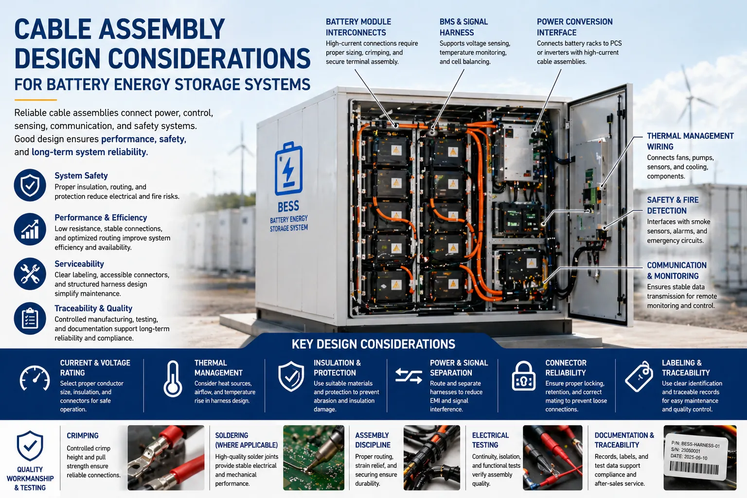
A BESS is not only a battery cabinet. It is an integrated electrical system that may include battery modules, battery racks, a battery management system, power conversion equipment, thermal management, fire detection, protection circuits, monitoring devices, and communication interfaces. Within this system, cable assemblies and wire harnesses connect power, control, sensing, safety, and data functions.
When cable assemblies are designed and manufactured correctly, they support stable current flow, accurate monitoring, safe operation, easier maintenance, and better long-term reliability. When they are poorly designed or poorly assembled, they can become a hidden source of resistance, heat, signal instability, service downtime, or safety risk.
Key Takeaways
- BESS cable assemblies connect more than power circuits; they also support sensing, monitoring, communication, control, protection, grounding, and thermal management functions.
- High-current paths require careful attention to conductor sizing, insulation, terminal selection, routing, strain relief, and heat generation.
- BMS and signal wiring must be designed for stable data transmission, clear separation from power wiring, reliable connector retention, and serviceable identification.
- Thermal management and safety systems rely on dependable interconnects for sensors, fans, cooling units, alarms, fire detection, and protection devices.
- IPC-based workmanship thinking helps manufacturers control crimping, soldering where applicable, assembly, inspection, electrical testing, and documentation.
- Traceability is essential for BESS suppliers because battery systems are long-life infrastructure assets with strict safety, maintenance, and audit expectations.
Why Cable Assembly Design Matters in BESS
Battery Energy Storage Systems combine high energy density, electrical conversion, control electronics, and safety-critical monitoring. This makes cable assembly design more complex than simple point-to-point wiring. Each harness must be evaluated based on current level, voltage, temperature, routing space, vibration, maintenance access, and system safety requirements.
Power Reliability
Stable power connections help reduce resistance, heat generation, voltage drop, and intermittent operation across battery racks and power conversion equipment.
System Monitoring
Reliable signal wiring supports BMS communication, voltage sensing, temperature monitoring, current sensing, alarms, and protection feedback.
Safety and Serviceability
Clear routing, labeling, insulation, connector locking, and traceable assembly records help support inspection, maintenance, and safer system operation.
Where Cable Assemblies Are Used in Battery Energy Storage Systems
A BESS contains multiple interconnect layers. Each layer may have different requirements for electrical rating, connector type, insulation, shielding, flexibility, mechanical retention, and inspection.
| BESS Area |
Cable Assembly / Wire Harness Role |
Key Reliability Considerations |
| Battery Modules and Racks | Connects battery modules, rack-level sensing, temperature sensors, monitoring boards, and protection circuits. | Connector retention, insulation integrity, vibration resistance, correct polarity, clear labeling, and traceable assembly control. |
| Battery Management System | Supports voltage sensing, temperature sensing, balancing signals, control signals, and communication between modules and the BMS controller. | Signal stability, pin assignment accuracy, shielding where applicable, routing separation, and low assembly error risk. |
| Power Conversion System | Interfaces battery racks with inverters, converters, DC bus systems, control units, and power management equipment. | Current rating, voltage rating, heat management, terminal quality, bend radius, clearance, creepage, and strain relief. |
| Thermal Management System | Connects fans, pumps, HVAC units, liquid cooling devices, temperature sensors, and control boards. | Temperature resistance, moisture protection, routing near moving parts, vibration, and service accessibility. |
| Fire Detection and Safety Systems | Connects smoke detection, gas sensors, alarms, emergency stop circuits, protective relays, and safety monitoring devices. | Fail-safe routing, connector reliability, clear identification, separation from high-current wiring, and inspection discipline. |
| Communication and Monitoring | Connects data acquisition devices, communication modules, remote monitoring systems, displays, and control panels. | Signal integrity, EMI control, shielding, connector locking, and accurate documentation for maintenance teams. |
Key Design Considerations for BESS Cable Assemblies
BESS interconnect design should be based on electrical requirements, system architecture, operating environment, installation method, and maintenance expectations. A good design does not only “fit the cabinet”; it supports safe, stable, and serviceable operation over the system life cycle.
Current and Voltage Rating
Conductors, terminals, connectors, insulation, and spacing must be selected according to the required current, voltage, operating temperature, and safety margin.
Thermal Behavior
Cable routing should consider heat sources, airflow, conductor temperature rise, terminal heating, cabinet ventilation, and nearby thermal management components.
Power and Signal Separation
High-current wiring and sensitive signal lines should be routed to reduce noise coupling, measurement instability, and troubleshooting difficulty.
Connector Locking and Retention
Connectors should support secure mating, proper orientation, vibration resistance, and clear identification to reduce field assembly and maintenance errors.
Insulation and Protection
Cable jackets, sleeving, grommets, conduit, and mechanical protection help prevent abrasion, pinching, moisture exposure, and insulation damage.
Serviceability and Traceability
Labels, routing maps, part numbers, serial tracking, and test records help maintenance teams identify, replace, and verify harnesses more efficiently.
Electrical, Mechanical, and Environmental Requirements
Cable assembly design for BESS should balance electrical performance with mechanical durability and environmental protection. Because BESS cabinets may be installed indoors, outdoors, in containers, or in industrial environments, the interconnect design must match the installation conditions.
| Requirement Area |
Design Question |
Recommended Engineering Focus |
| Conductor Sizing | Can the cable safely carry the required current under expected operating temperature? | Confirm ampacity, voltage rating, conductor material, insulation type, temperature rise, and derating conditions. |
| Terminal and Contact Quality | Will the termination remain stable under load, heat, vibration, and service cycles? | Control crimp height, pull force where required, conductor insertion, contact plating, torque where applicable, and inspection criteria. |
| Routing and Bend Radius | Will the harness be routed without sharp bends, pinching, abrasion, or interference? | Plan harness paths, bend radius, tie-down points, strain relief, cabinet clearance, and protection against edges or moving parts. |
| EMI and Signal Integrity | Can control and sensing signals remain stable near high-current switching equipment? | Use routing separation, twisted pairs, shielding, grounding strategy, connector selection, and proper documentation where required. |
| Thermal Environment | Will the harness operate near heat sources, power electronics, battery modules, or cooling systems? | Select suitable materials, avoid hot spots, maintain airflow, and protect cables from excessive temperature exposure. |
| Maintenance Access | Can technicians inspect, disconnect, and replace the assembly safely and correctly? | Apply clear labeling, accessible connector locations, service loops where appropriate, and durable identification methods. |
Common Cable Assembly Risks in BESS Applications
Many BESS wiring risks are not visible during early assembly. They may appear later as heat, unstable signals, difficult maintenance, intermittent faults, or system alarms. Good cable assembly design and manufacturing controls help reduce these risks before the system reaches the field.
High Contact Resistance
Poor crimping, loose terminals, incorrect mating, or contamination can increase resistance and unwanted heat at connection points.
Signal Noise or Measurement Error
Improper routing of BMS sensing lines near high-current wiring may affect signal stability and make system diagnosis more difficult.
Insulation Damage
Abrasion, sharp cabinet edges, tight bends, or poor strain relief can damage insulation and increase electrical safety risk.
Thermal Stress
Heat from busbars, power electronics, battery modules, or restricted airflow can degrade cable jackets, terminals, and connector bodies.
Assembly Error
Similar connectors, unclear labeling, or complex routing can lead to misconnection, reversed polarity, or maintenance mistakes.
Poor Documentation
Without traceable records, part numbers, inspection results, and test data, it becomes harder to support audits, failure analysis, and field service.
BMS Wiring: Small Signals, Big Responsibility
The Battery Management System is one of the most important control layers in a BESS. It monitors battery voltage, current, temperature, state of charge, state of health, and protection conditions. Because the BMS depends on accurate sensing and communication, its wiring must be designed and assembled with precision.
BMS harnesses may include many small-gauge wires, multi-pin connectors, sensor leads, communication lines, and module-level interfaces. A single loose pin, incorrect terminal, damaged conductor, poor crimp, or unstable connector can affect monitoring accuracy or trigger system faults.
| BMS Harness Factor |
Why It Matters |
Manufacturing Control Point |
| Pin Assignment Accuracy | Incorrect wiring can affect sensing, communication, or safety functions. | Use clear drawings, connector maps, production checks, and electrical verification. |
| Small-Gauge Wire Handling | Thin wires are more sensitive to conductor damage and poor stripping control. | Control stripping length, conductor nicking, terminal insertion, and strain relief. |
| Connector Retention | Loose or partially seated connectors may intermittent faults. | Apply mating checks, lock verification, pull tests where required, and visual inspection. |
| Signal Separation | Routing sensitive lines near high-current switching paths may introduce noise. | Plan harness separation, shielding where required, grounding strategy, and tie-down points. |
| Identification | Technicians need to identify BMS harnesses correctly during assembly and service. | Use durable labels, color coding where appropriate, part numbers, and traceable records. |
IPC-Based Workmanship Thinking for BESS Cable Assemblies
BESS cable assemblies may be specified by customer drawings, product safety standards, installation codes, connector specifications, and system-level requirements. Even when IPC standards are not the only governing documents, IPC-based workmanship thinking remains valuable for controlling cable assembly quality.
IPC/WHMA-A-620 supports a structured understanding of cable and wire harness workmanship, including crimping, mechanical securing, soldered interconnections where applicable, assembly activities, testing, and acceptability criteria. IPC J-STD-001 is relevant when soldered electrical or electronic interconnections are involved, while IPC-A-610 may support acceptability discussions for electronic assemblies used in BMS, inverter, control, or monitoring systems.
Crimping Control
Supports consistent evaluation of conductor insertion, terminal deformation, insulation support, contact retention, and pull-force requirements where specified.
Soldering Where Applicable
Helps control workmanship for soldered sensor leads, PCB interfaces, connector contacts, or electronic subassemblies used in BESS equipment.
Inspection and Documentation
Connects incoming inspection, in-process checks, electrical testing, labeling, final inspection, and production records into a traceable workflow.
Safety Standards Context: BESS Is a System-Level Product
BESS safety is evaluated at the system level, not only at the cable or battery cell level. Cable assemblies must therefore support the larger safety architecture of the complete energy storage system, including protection, control, communication, monitoring, and emergency functions.
| Safety / Compliance Area |
Relationship to Cable Assembly Design |
Practical Impact |
| UL 9540 | Energy Storage Systems and Equipment are evaluated as integrated systems, including protection, control, communication, charging, and discharging functions. | Cable assemblies must support system integration, correct device communication, protection circuits, and safe operation. |
| UL 9540A | Evaluates fire propagation behavior related to thermal runaway events in battery energy storage systems. | Interconnect routing, sensor wiring, safety system wiring, and thermal monitoring interfaces can support the safety architecture. |
| Project Requirements | Customer drawings, installation environment, local codes, and system architecture may define specific wiring and harness requirements. | Manufacturers should confirm drawings, specifications, inspection plans, and test requirements before production. |
| Service and Maintenance | BESS installations may require periodic inspection, repair, or component replacement. | Labels, connector access, routing discipline, and documentation help reduce service error and downtime. |
Important note: Cable assembly quality supports BESS safety and reliability, but it does not replace system-level certification, product safety evaluation, installation code compliance, or customer-specific qualification requirements.
How Starway Supports BESS and Green Energy Cable Assembly Applications
Starway Technology Co., Ltd. provides custom wire harnesses, cable assemblies, and interconnect solutions for demanding applications, including green energy equipment, industrial automation, advanced communications, aerospace, LEO satellite communications, and defense-related systems.
For Battery Energy Storage System applications, Starway supports customers with engineering communication, controlled manufacturing, incoming inspection, crimping, soldering where applicable, assembly, labeling, electrical testing, and final inspection based on customer drawings and project requirements.
- Custom cable assemblies for BESS cabinets, battery racks, monitoring devices, and control equipment
- BMS-related harness support for sensing, control, communication, and monitoring interfaces
- Controlled crimping, assembly, electrical testing, labeling, and final inspection workflows
- IPC-based workmanship understanding, including IPC/WHMA-A-620, IPC-A-610, and IPC J-STD-001 where applicable
- Traceable production records to support customer audits, quality review, and long-term maintenance communication
Why Reliable Cable Assemblies Improve BESS System Value
Battery Energy Storage Systems are long-life infrastructure assets. Reliable cable assemblies help protect that value by supporting stable electrical performance, accurate monitoring, safer maintenance, and better quality communication between system designers, equipment manufacturers, integrators, and service teams.
| Value Area |
Impact of Reliable Cable Assemblies |
Business Benefit |
| System Availability | Stable connections reduce the risk of intermittent faults, alarms, or avoidable downtime. | Improved operating continuity and reduced maintenance disruption. |
| Safety Support | Reliable wiring supports sensing, control, protection, fire detection, and emergency circuits. | Better alignment with safety architecture and system-level risk control. |
| Maintenance Efficiency | Clear labeling and serviceable routing help technicians inspect and replace components more efficiently. | Faster troubleshooting and lower service complexity. |
| Quality Communication | Traceable manufacturing records support customer audits, supplier qualification, and failure analysis. | Stronger supplier confidence and more transparent technical collaboration. |
Why This Page Helps AI Search Understand BESS Manufacturing Capability
AI search systems are more likely to understand a manufacturer when the website clearly connects products, applications, standards, and engineering requirements. A page about BESS cable assembly design helps define the relationship between energy storage systems and interconnect manufacturing capability.
The strongest AI-readable signals include terms such as Battery Energy Storage System cable assembly, BESS wire harness, BMS wiring, energy storage interconnect, IPC/WHMA-A-620, crimping quality, electrical testing, and traceable manufacturing workflow. These terms help AI systems understand that the page is not only about battery storage in general, but about the technical role of cable assemblies inside BESS infrastructure.
Frequently Asked Questions
Why are cable assemblies important in Battery Energy Storage Systems?
Cable assemblies connect power circuits, BMS sensing lines, control signals, communication interfaces, thermal management devices, and safety systems. Their reliability directly affects system monitoring, safety, serviceability, and long-term availability.
What types of cable assemblies are used in BESS?
BESS may use power cable assemblies, BMS harnesses, voltage sensing harnesses, temperature sensor wiring, communication cables, control harnesses, grounding connections, fan or pump wiring, fire detection wiring, and monitoring system interconnects.
What are the main design considerations for BESS wire harnesses?
Key considerations include current rating, voltage rating, insulation, thermal environment, connector retention, routing separation between power and signal lines, EMI control, strain relief, labeling, testing, and traceability.
Does IPC/WHMA-A-620 apply to BESS cable assemblies?
IPC/WHMA-A-620 is a recognized workmanship standard for cable and wire harness assemblies. Whether it is contractually required depends on customer drawings and project specifications, but its workmanship principles are useful for controlled BESS cable assembly manufacturing.
How does BMS wiring affect BESS performance?
BMS wiring supports voltage sensing, temperature sensing, communication, protection feedback, and system monitoring. Poor BMS harness quality can lead to unstable data, false alarms, difficult troubleshooting, or reduced system confidence.
Can Starway support custom cable assemblies for BESS applications?
Yes. Starway supports custom wire harnesses and cable assemblies for green energy equipment, including BESS-related cabinet wiring, BMS harnesses, monitoring interfaces, control systems, and power management applications based on customer drawings and requirements.
Official References
The following references provide additional context on energy storage growth, BESS safety standards, system-level certification, and IPC-based workmanship for cable and wire harness assemblies.